

Custom Welded Equipment Base and Machine Frame for Industrial Machinery
A welded equipment base is the structural interface between a machine and the floor it stands on. Tianhua Yihe fabricates custom bases and machine frames to customer drawings, combining plate cutting, fixture-assisted welding and post-weld machining so that the geometry that actually matters - pad height, hole position, face flatness - is established after the heat of welding rather than before it.
 An equipment base after welding: gusseted box-section structure with four mounting pads left with machining allowance.
| Component type | Welded equipment base, skid frame, machine frame, sub-frame with mounting pads |
|---|---|
| Typical materials | Q235B, Q345B / Q355B carbon steel; 304 / 316L stainless on request |
| Cutting | Laser cutting, plasma cutting, flame cutting for heavy plate |
| Forming | Press-brake bending, rolled sections where required |
| Welding | MIG, TIG, and manual arc as applicable to the joint and material |
| Machining | Post-weld CNC machining of pads, faces, bores, slot and hole patterns |
| Finish | Painting, powder coating or hot-dip galvanizing through qualified partners |
| Order type | Prototype, first article, and repeat production batches |
What an equipment base actually has to do ?
A base or machine frame carries four separate jobs at once, and a fabrication plan that only addresses one of them will usually fail inspection on another:
Transfer load to the foundation. Static weight, dynamic and out-of-balance forces, and torque reaction all pass through the frame into anchor points or levelling feet.
Hold the mounting interface. Pad height, pad flatness, hole pitch and bore position determine whether the machine sits square and whether shafts, couplings and drives align.
Provide access. Fastener access, lifting points, jacking points, drain and cable routing, guarding attachment and maintenance clearance all have to survive the welding sequence.
Survive the environment. Indoor paint systems, outdoor coatings, washdown, galvanizing and coastal exposure each impose different preparation requirements.
Most field problems with fabricated bases trace back to the second job. A frame can be welded square, pass a tape-measure check, and still refuse to accept the machine because two pads are 1.5 mm out of plane or a hole pattern has crept 2 mm on centres.
Why mounting interfaces are machined after welding ?
Welding moves metal. A fillet weld on one side of a stiffener pulls that stiffener toward the weld; a long seam shrinks longitudinally and bows the plate; a pad welded on four sides dishes toward the weld metal. These movements are predictable in direction but not in magnitude, because they depend on heat input, pass sequence, restraint and fit-up gap.
The practical consequence is a sequencing rule: anything that must be accurate is machined after the weldment is complete. Mounting pads are left with machining allowance, welded, straightened where necessary, stress-relieved when specified, and only then faced, milled or bored. General fabricated dimensions can be controlled during fit-up and checked with a tape or a laser; critical installation interfaces cannot.
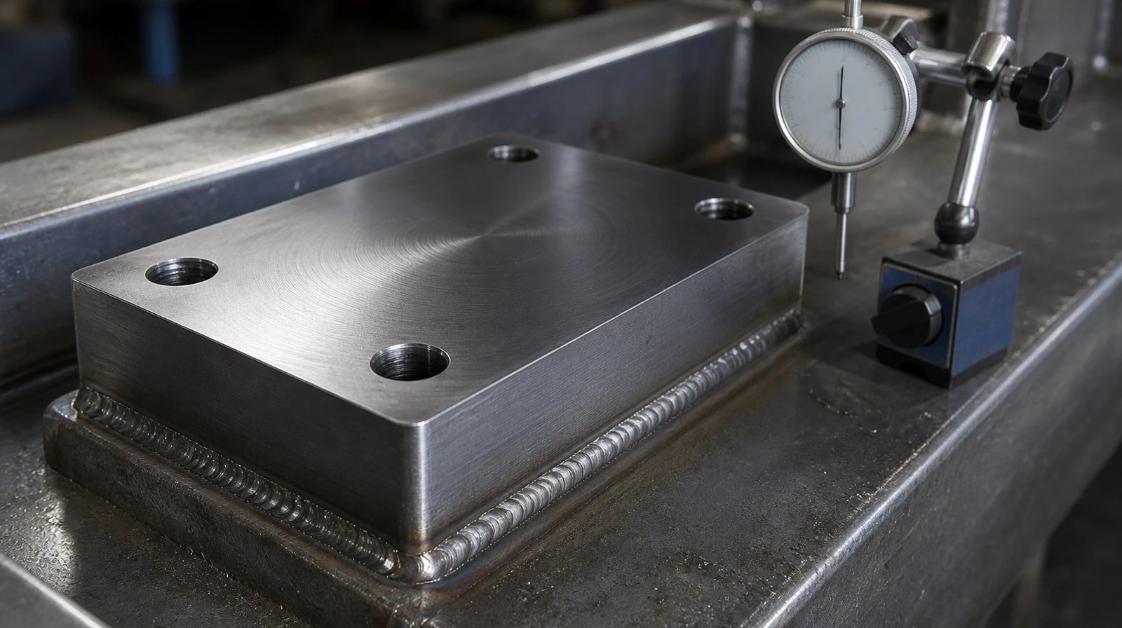
A pad machined after welding: the face is cut and the hole pattern established on the finished weldment, not on the cut parts.
Manufacturing route
| Step | Operation | Control point |
|---|---|---|
| 1 | Drawing and model review | Weld access, machining allowance, datum scheme, lifting and transport limits |
| 2 | Material preparation | Grade and thickness verification against mill certificate, plate identification |
| 3 | Cutting | Nesting from DXF/model, hole and edge quality per drawing |
| 4 | Forming | Bend line position, angle, and springback compensation |
| 5 | Fit-up in fixture | Squareness, diagonal equality, pad elevation relative to datum |
| 6 | Welding | Weld size, sequence per welding plan, interpass condition |
| 7 | Stress relief (if specified) | Partner furnace cycle, record retained |
| 8 | Straightening and dimensional check | Frame geometry before machining, allowance confirmed |
| 9 | Post-weld machining | Pad flatness and height, hole position, bore alignment |
| 10 | Trial assembly | Interface fit with mating parts where supplied or specified |
| 11 | Surface treatment | Partner process, DFT and appearance |
| 12 | Final inspection and packing | Dimensional report, protection of machined faces, lifting and lashing plan |
Distortion control measures
Distortion control is not a single operation; it is a set of decisions taken before the first arc is struck.
Weld size discipline
Oversized fillets are the most common avoidable cause of base-frame movement. Where the drawing permits, the smallest leg length that satisfies the design requirement is used, because heat input scales with deposited volume. A 6 mm fillet where the design needs 5 mm adds roughly 40% more weld metal and a corresponding amount of shrinkage.
Balanced and sequenced welding
Welds are grouped so that shrinkage on one side of a member is opposed by shrinkage on the other. Long seams are run with backstep or alternating direction; stiffener groups are welded as sub-assemblies and allowed to cool before being joined into the main frame. The welding plan is written per assembly, not per drawing sheet.
Fixture restraint and pre-setting
Frames are fitted and initially welded in a fixture that holds the datum features. Where the design allows, members are pre-set against the expected shrinkage direction - a small camber or a slight over-angle - so the frame straightens as it cools instead of bowing away from the datum.
Sub-assembly before final weld
Cutting the frame into manageable welded sub-assemblies limits accumulated error and makes each group accessible for welding, grinding and inspection. It also matches the frame to the boring and lifting capacity available at each stage.
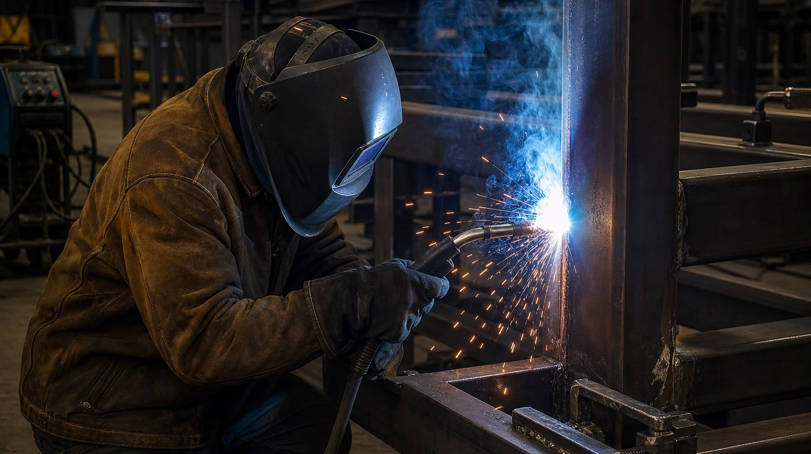
Welding in a fixture: sequence and restraint are planned per assembly to limit movement before machining.
Access for welding, grinding and inspection
A joint that cannot be reached cannot be welded properly, and a weld that cannot be seen cannot be inspected. During drawing review, closed box sections, pad-to-plate joints and stiffener-to-flange connections are checked for torch angle, electrode reach and visual access. Where access is inadequate, the usual remedies are a weld access hole, a changed stiffener profile, or a revised assembly sequence - all of which are cheaper to agree before cutting than after.
Machined interfaces and datum strategy
Correct machining depends on a datum scheme that survives fabrication. In practice this means:
Nominate one primary machining datum, usually the underside of the base plate or a machined face, and carry it through fit-up, welding and inspection.
Leave 3–6 mm of allowance on pads and faces that will be cut, depending on frame size and expected movement.
Machine related features - pads that share a plane, bores that share an axis - in one set-up wherever the frame fits on the machine table.
Record the as-machined values, not just pass/fail, so that a repeat order starts from measured data.
Where a frame is too large for a single set-up, pads are machined in groups with the datum re-established between set-ups, and the positional relationship between groups is verified on the finished part.
Materials and standards
Carbon steel grades Q235B, Q345B and Q355B cover most equipment-base work. Stainless 304 and 316L are used where washdown, chemical exposure or hygiene requirements apply. Plate thickness and section selection remain the designer's responsibility; the fabrication review checks that the specified material can be cut, formed, welded and machined as drawn.
Where the purchase order calls for them, fabrication and inspection can be executed to general dimensional tolerances such as ISO 2768-mK, weld acceptance criteria such as ISO 5817 or AWS D1.3, and galvanizing to ISO 1461. Mill test certificates to EN 10204 2.2 or 3.1 can be supplied for traceable material. None of these are applied by default - the applicable standard is confirmed at quotation, because the same frame inspected to two different criteria is two different prices.
Inspection and documentation
Inspection points are defined per project. For a typical base or frame they cover:
Material identification against certificate and drawing
Cut part dimensions and hole quality
Pre-weld fit-up: squareness, diagonals, pad elevation, gap
Weld visual inspection, leg length and throat measurement, weld map reference
Non-destructive testing - magnetic particle, penetrant or ultrasonic - through a qualified partner when specified
Post-machining: pad flatness, height, hole position, bore alignment
Coating thickness and adhesion through the finishing partner
Final photographs before packing
The documentation package can include the dimensional inspection report, material certificates, weld inspection records, NDT reports, coating certificate, packing list and pre-shipment photographs. It is assembled per order, not issued as a generic certificate.
Packing and transport
Bases are heavy, awkward and easy to damage at exactly the surfaces that took the most work to produce. Machined pads are coated with rust preventive, bores and threads are capped, and the frame is blocked so that it rests on structural members rather than on machined faces. Lifting points are marked, and the lashing arrangement is planned against the frame's own stiffness so that transport loads do not pull the base out of square.
Frequently asked questions
What drawing formats can you work from?
STEP, IGES, Parasolid, DXF, DWG and PDF drawing packages are all workable. For machined mounting interfaces a 3D model is strongly preferred, because hole positions and pad heights can then be checked in the model rather than interpreted from an annotated 2D view.
Do you machine mounting pads after welding?
Yes. When the drawing specifies flatness, parallelism or position tolerances on mounting pads, bores or faces, those features are machined after the weldment is complete and, where required, after stress relief. Machining before welding would let shrinkage pull the interfaces out of tolerance.
How do you control welding distortion on a large frame?
Distortion is managed by weld size discipline, a balanced and sequenced welding plan, fixture restraint during fit-up, sub-assembly of stiffener groups, pre-setting of camber where the design allows, and straightening before final machining.
Can you supply stress-relieved frames?
Thermal stress relief can be arranged through a qualified heat-treatment partner before final machining when the drawing or specification calls for it. The requirement needs to be stated at enquiry stage so it is built into the process route and the quotation.
What is the minimum order quantity?
Single units and prototypes are supported. Quantity affects how much fixturing and program preparation is worth building, so the economic batch size depends on the drawing, the number of machined interfaces and the material. Send the drawing and intended quantity for a specific answer.
How are machined surfaces protected during shipping?
Machined faces receive a rust-preventive coating, exposed bores and threads are plugged or capped, and the base is blocked and strapped on a skid so that pads and alignment features carry no load in transit. VCI film and wooden cribbing are used where the route or the climate requires it.
Send a base drawing for manufacturability review
Useful information to include: the drawing or 3D model, material grade, critical mounting dimensions and tolerances, quantity, surface finish requirement, delivery destination and target date. We reply with a process route, the points we would change for manufacturability, and a quotation.
Email: andywang@qdthyhmetalfab.com
Qingdao Tianhua Yihe Metal Fabrication - sheet metal and welded fabrication for OEM equipment builders.